Sunday, December 4, 2011

So... How do I plug this thing?

Previous experience with several devices makes us worry about a compatibility issue that may affect the electric car: How to plug it to the power grid for recharging?. It seems a simple issue, but we'll see it's not.

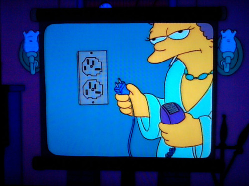
The geographical area determines the type of connection to the grid in its form, frequency and voltage. This causes serious difficulties when travelling, as it became evident in the Patty’s honeymoon video in The Simpsons.


But, even with unified power grid plugs, various daily use devices such as laptops or mobile phones have a variety of chargers and connectors. When thinking about the purchase of an electric vehicle, its compatibility with public charging facilities or future charging technologies can be a serious concern. In this sense, work is being done toward standard and unified systems. Although this goal has not been completely achieved, some options have been introduced and the most widespread standard will probably arise among them.


In addition, electric vehicle charging involves a high energy consumption.To get an idea, a slow charge (which takes less power) usually needs about 16 amps at single phase 220 V outlet in Europe. This means a maximum consumption of about 3.5 kW. In American power system that power is halved for a 110 V outlet, but the charge time doubles. The most powerful devices we use every day, such as a hair dryer, a heater, an electric water heater, an oven... usually need a power figure below 3.5 kW. Even the basic power limit that can be hired for a home in Spain is less than this value. If you want to charge the car faster, the power should increase and a three-phase connection becomes necessary. So it’s not only about standardization, because safety is also required in the operation due to the high power systems involved.


When considering the installation of charging points for electric vehicles, choices have to be made between several options that depend on conditions such as the available electrical infrastructure, the location, the intended use...
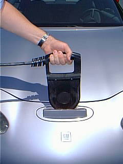
There are 2 main technologies: the conductive and inductive charging.


  • Main advantage of inductive systems is that no electrical contacts are needed. Different proposals have been introduced and some of them carry out the installation of the system under the garage floor to charge a vehicle parked over it. On the other hand,  their performance is low and its use is less widespread.


  • The conductive charge is based on electrical contacts, as in any plug. It’s performance is high and, nowadays, it’s a widespread technology. Its main features are described below.

The most widespread standard that regulates the details related to the conductive charging process is known as IEC 62196. It defines the technical features, including communication systems between the vehicle and the station, but it doesn’t include standards for connectors. It’s defined by the International Electrotechnical Commission (IEC). Often, each plug design includes its own protocol for communication and charge, but all can be related to the definitions made by IEC 62196. In it, 4 categories are defined to characterize the charging mode:

-Mode 1, slow charge using a household socket-outlet:


This mode defines the charge from the AC power grid through household outlets not exceeding 250 volts for single fase AC or 480 volt for three phase AC. Control contacts are not required and more restrictive local regulations should be fulfilled. In some cases, such as USA, this type of charge is prohibited because not all household outlets have the necessary protective earth.

-Mode 2, slow or fast charge using a household electrical outlet with a protective and control device embedded in the connection wire:


In this case the grid supplies also single phase AC to 250 volts and 32 amps and 480 volts and 32 amps for three-phase. Protective earth is needed and the control device located between the household outlet and the vehicle has a management contact that communicates with the car and regulates the charge based on several parameters.

-Mode 3, slow or fast charge through outlet with specific equipment and control and protection functions embedded:


This mode uses a dedicated equipment which is permanently connected to AC power. These devices need different signal and control contacts on both ends of the cord and the system avoids the voltage on the vehicle’s connector if it is not plugged. In addition, communication between vehicles and stations makes possible the integration into “smart grid” distribution systems.

-Mode 4, fast charge using an external charger:


In previous modes the electrical outlet was equipped  with different degrees of complexity, but the charging process is always done using an in-vehicle system, which adjusts the electric power and converts electricity to get the DC current which is supplied to the batteries. In mode 4, these processes are carried out by the charging station, which provides DC current to the vehicle, achieving the fastest charges.

The management, safety and possibilities increase with mode number, but the device cost is more expensive.

Within these modes, different types of connectors are designed. They have high protection indexes that make possible its daily use. The most common designs are listed below:

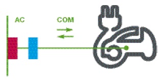
•Type 1: SAE J1772 or Yazaki..


This connector is proposed by the Society of American Engineers, SAE and it’s the standard in USA. It encompasses not only physical but the device itself and the communication protocols used. This is the connector appearance:


It’s based on a 43 mm (1.7 inches) round shape and it’s composed by 5 pins: 2 for AC line (same size), one protective earth, one for proximity control (prevents the car from moving when connected) and one for control purposes. The control connector uses a square wave (+ -12 V) of 1 kHz frequency that controls the vehicle's presence, regulates the maximum permissible current intensity and the whole process. The position of these pins on the connector is shown in the following picture:


It is designed for several levels of AC power:
•Level 1: 120 volt single phase supply and up to 16 amps (up to 2 kW)
•Level 2: Split-phase 240 volts systems and up to 80 amperes (up to 19 kW).

This system can be used in mode 2 or mode 3.
Later, a different configuration with additional DC current and protective earth pins is introduced. It can provide 36 kW of power at 200-450 volts DC at the first level and up to 90 kW with 200 amps DC for level 2.


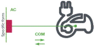
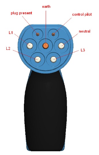
-Type 2: VDE-AR-E 2623-2-2 or Mennekes.


Mennekes is a German company which makes electrical components. It has proposed a standard protocol and vehicle charging connector, which has a good chance of being the standard in Europe.
The appearance of the connector is shown in the image below.


It consists of 7 contacts arranged in a round shape of 55 mm. (2.2 inches) with a flat area. The set of contacts includes 3-phase AC, one neutral,one protective earth and two signal pins. One is to handle the communication between the vehicle and the charging station and the other one detects the car presence. These pins are identified in the picture below:


This charging system is connected to the AC grid, either in Mode 2 or Mode 3, with the following characteristics:

  • Single phase, 230 volts up to 16 amps (up to 3.7 kW).
  • Three-phase, 380 volts up to 63 amps (up to 43.8 kW).


-Type 3: Scame or EV Plug Alliance.


This connector is created by the EV Plug Alliance, a group formed by Schneider, Legrand and Scame, and it’s also known as Scame connector. This is another strong bet to implement electromobility in the European market.


It can provide single-phase charge at 220 volts or three phase at 380 volts up to 22.2 kW (up to 32 amps at 400 volts three-phase).


It can include 5 or 7 contacts in the connector, consisting of the 3 phases, neutral, protective earth and 2 pins to communicate with the docking station. This connector is designed mainly for mode 3.


-Tipo 4: TEPCO - JARI - CHAdeMO


CHAdeMO is an association formed by Tepco, Nissan, Mitsubishi, Fuji Heavy Industries (maker of Subaru) and Toyota. The standard CHAdeMO allows fast charge with direct current, so, it moves the conversion and rectification of current outside the vehicle and provides DC power directly to batteries. This system achieves the fastest charging and it’s an international technology for this kind of process. The connector used is shown below and it’s also called Jari or TEPCO, as it has been established by the Tokyo Electric Power Company.


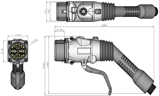
The connector has 10 contacts. The two with a larger diameter are the positive and negative poles that provide DC current and the other 8 are a combination of analog and digital communications for charging management and control. The most important physical connections in this system are shown in the image below:


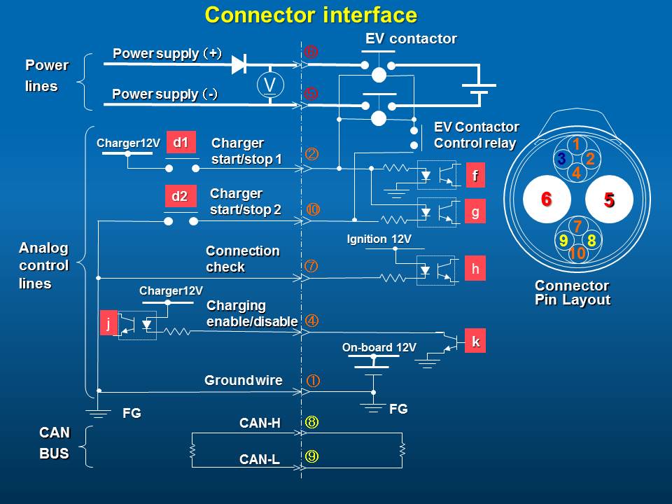
This system is a mode 4 and provides a maximum current of 100 amps at 500 volts DC, which means up to 50 kW. This high power requires the charging station to be connected to the high voltage grid, usually with a dedicated transformer.

These are the main systems that are now on the market. Probably, in the future, some of them will become standard and others will disappear, but now they are doomed to coexist. So, the manufacturers will have to monitor their evolution to avoid your car model to become the next HD-DVD.


  • Sources:

Info about standard IEC 62196
Wikipedia

Conectors IEC 62196
Forococheselectricos.com

Mennekes
Información Mennekes

Scame
ecomove.es
Schneider-electric
Scame

Information about standard TEPCO - CHAdeMO
Wikipedia
International Energy Agency
Chademo


  • Images:

Patty:
http://eyeonspringfield.tumblr.com

Cell phone chargers:
http://www.celulais.com/

Grames:
http://plusplusdance.tumblr.com/

Inductive charge:
http://gajitz.com/look-mom-no-cord-induction-charger-for-electric-cars/

Charge modes
Schneider-electric

SAE J1772
http://carstations.com/types/j09
http://www.sae.org/mags/aei/enrg/7479

Mennekes
Bluemobility
http://elbil.pbworks.com/f/MENNEKES%2Band%2BEV.pdf

Scame:
Scame.com
Evplugalliance

CHAdeMO:
Thetruthaboutcars
http://www.uppladdning.nu/OutletsInfo.aspx
Chademo.com

Monday, August 15, 2011

GM EV1

The EV1 was GM’s attempt to electrify cars about mid 90’s, sold trough Saturn dealerships. It came out as a response to CARB (California Air Resources Board) that forced major car manufactures to offer a zero emission vehicle. EV1 was one of many models that came out, such as Ford Ranger EV, Toyota Rav4 EV, Chevrolet S10 EV, Honda EV plus or Nissan Altra EV (R’nessa). It was introduced at 1990 Los Angeles auto show as a prototype called Impact.
General Motors made a huge technical and economical effort to develop EV1, that turn out into a symbol that remained for more than a decade. Nowadays, when talking about Chevrolet Volt / Opel Ampera, many references are made to GM’s pioneer in electric cars and once-official EV1 website (www.gmev.com) introduces the new model of the Detroit giant without a mention to the original model.

Outside
A whole new aluminum chassis, suspension and wheels were designed for the EV1. Thus, weight was reduced to 1910 pounds (865 kg) without batteries.
Main dimensions were: length 169 inches (4’31 meters), width 70 inches (1’76 meters) and height 50 inches (1’28 meters).
Exterior car panels were made from light, dent resistant plastic  and they formed a teardrop shape, where front axis was wider than the rear one, as the Citröen DS. This configuration and special low rolling resistance and self-sealing 175/65 R14 tires inflated to 50 psi (3’45 bar) contributed to a poor dynamic performance. But this body reduced aerodynamic resistance, achieving an amazing 0’19 Cx (a current Prius has a 0’25 Cx) and a frontal area of 0’36 m2. Very low aerodynamic and rolling resistances were fit together to create an excellent eco car.

Interior
It was a two-seater vehicle with a quite generous trunk for its length. EV1 interior was even more advanced than the car. It’s futuristic appearance included a huge central area with the audio system, many buttons and the gear selector. Battery, speed, range and other info was available at the center screen on the dashboard. This interior design and the feeling of moving just with rolling and electric sound created an unique driving experience.

Power system and brakes
The car was moved by a 3-phase AC electric induction motor that was able to generate 102 kW (137 hp) at 7000 rpm. The torque was constant, 107 pound·feet (149 Nm) so gear shifting was unneeded. Power was translated to wheels though a single reduction gear.
Motor management was carried out by an inverter with isolated gate bipolar transistors (IGBT) power electronics.
It made 0 to 60 mph in 9 seconds and the top speed was electronically limited to 80 mph (129 km/h).
The estimated average consumption in kW·h/100 miles was 26 city/26 highway for lead-acid system and 34 city/30 highway for nickel metal hydride (Nimh) batteries.
It was equipped with hydraulic power brakes with embedded  regenerative braking and electric parking brake. Braking from 60 mph to stop was achieved in 160 feet (49 meters).

Batteries
It was available with lead-acid or nickel metal hydride (Nimh) batteries. Lead-acid battery system was worth $4800 its weight was 1175 pounds (530 kg). It was made by 26 batteries connected in series and arranged in a T shape between and behind front seats. First lead-acid system was made by Delphi, with units of 12V /53 A·h and a total capacity of 16’5 kW·h at 312 V that achieved a 60 miles (96 km) range. Generation 2, released in 1999, was equipped with a Panasonic lead-acid system, valve regulated, with 12V/60A•h units, total capacity of 18’7 kW·h at 312V that achieved a 100 miles (161 km) range. It was a 99% recyclable technology, but had a higher memory effect than Nimh.
The Nimh option was also made by Panasonic and its weight was 1000 pounds (450 kg) . As the lead-acid, it was arranged in a T shape between and behind seats with units connected in series. Each unit had 13’2V and 77 A·h, with a total capacity of 26’4 kWh at 343V, that achieved a 160 miles (257 km) range. The price of the Nimh battery pack is difficult to find, but it’s somewhere between $20000 and $35000, just as a good quality and properly equipped car. Its specific energy (kW·h/kg) doubled the lead-acid figures and, moreover, Nimh had lower degradation under high currents, lower cycling sensibility (equivalent to car’s service life) and better performance in low temperatures but worst in hot weather. The recycling process regenerates the whole product and allows the production of new batteries. But it was a very expensive technology that was supposed to reduce its price when it became a mainstream product. More than 10 years later, Toyota Prius batteries have a capacity of 1’3 kW·h with Nimh technology and the retail price is around $1500. Converting that price to the EV1’s 26’4 kW·h Nimh whole pack, the result is about $30500. So, either a much more mainstream battery as the Prius didn’t get a lower price for this technology or EV1 battery pack was even more expensive than it was estimated.
In addition to above-mentioned high voltage packs, EV1 had a 12V battery to supply power to accessories.

Charging system
EV1 could be charged by a conventional 110V 60Hz charger placed in the truck. An inductive charger was also available and it allowed a no contact charge without electric risk while acting as a transformer. But its efficiency was low when compared to the conventional charger. The inductive charger connection was located between front headlights.

Equipment
Most important equipment is: ABS, traction control, tire pressure control system, dual airbag, 3 points seatbelts, daytime running lights, keyless entry/start-up with security system, electrically heated windshield and rear window defrosting and defogging, power windows, power door locks, cruise control, AM/FM radio with CD player and climate control with heat pump.

And… how much is it?
The EV1 could only be purchased under a leasing contract, that included maintenance and service, including everything from batteries to tires, and a 3 year or 36000 miles warranty with 24 hour road assistance. Estimated retail price was around $34000 to $44000, depending on year and battery technology. Monthly leasing price was between $350 and $575. Electricity cost was from $2’5 to $3 per 100 miles, against $6’8 for an equivalent gas powered car.
But, if you want to buy one nowadays, you’ll have serious trouble. EV1 were removed in 2002. Leasing contracts weren’t renewed when reaching the expiration date and GM denied any buying option suggested by users, including the warranty or service cancellation. All vehicles were picked up by GM and crushed, with few exceptions that came to universities or museums. This generated a huge controversy in USA, that increased with lawsuits and patent acquisition in battery technology by oil companies and increasing pressure from federal government that softened legal conditions that boosted this EV fever in California. GM gave many reasons for this fact, some with low credibility and others more sensible. Anyway, the most innovative GM project was ended in a non-dialogist way while other makers such as Toyota or Ford knew how to look for formulas to sell their vehicles after leasing.
A very interesting look at this history of a huge step forward and its early death were summarized in a very recommendable documentary: “Who killed the electric car?” (http://www.whokilledtheelectriccar.com/), directed by Chris Paine in 2006. Here are the links to english and Spanish sources. The second part of this documentary has just been released: “Revenge of the electric car” (http://www.revengeoftheelectriccar.com) and it reviews how it reemerged from its ashes over last years through the efforts of 4 men to build a successful electric vehicle.

Until next post, I leave you these videos to get a deeper idea of what this iconic car meant and still means:
-Promotional video
-Commercial
-The Simsons commercial. Homer agreed to do a test drive, as Lisa requested. He concluded he didn’t like the car after driving it underwater.
-One car recovered and restored
-Some information about the vehicle and its use, including some troubles with nominal and real range.


Sources:


Images:


Wednesday, July 27, 2011

Solutions with sparks

Electrification of vehicles already seems unstoppable. This involves advantages such as the total or partial decrease of tailpipe emissions, the capacity to cover with renewable energy a fraction of transport consumption, more efficient use of energy thanks to improvements suchs as regenerative braking or traffic noise level reduction. However, problems also arise, like increase of long term electric demand, the need to generate that energy and the emissions of that process, full electric vehicles low range of use and a dramatic change for after-sale services technology used during last decade.
These are just some arguments for and against this challenge. But, how should mainstream components such as power electronics, batteries and motors be suddenly implemented?. It’s a difficult task and there’s only one way to face it: step by step. Despite attempts for full electric vehicles have already been made, like the one from CARB in mid-nineties, it still hasn’t become a mainstream technology. However, electric car parts and gas engines have been mixed during last decade and hybrid car technology was created and widely implemented. During last year several fully electric cars have been introduced, fully replacing gas engines. Available setups for these electric vehicles are shown below.

Electric vehicles: Silent power

Electric vehicles use electric motors to move. Depending on their layout, three configurations can be defined [1]:

  • Those which move always by external energy. Electric motors and power electronics for management are incorporated, but energy is taken from external sources continuously. A complex infrastructure is needed to supply electric energy.
  • Those which store external energy to use it later. Systems are quite similar to previous category, but energy is stored in batteries.
  • Those which employ a different energy source to generate all or a part of the electricity used by the car (hybrid electric vehicles). In some cases they can store electricity from external sources, but a generator to create energy for the batteries is always present. This generator can be either a conventional group engine – alternator or a fuel cell using hydrogen.

The last group has many alternatives that are detailed below.

Hybrid vehicles: Mixing volts with octane

Definition for a hybrid vehicle is “that has two or more major sources of propulsion power” [2]. This creates several types of hybrid vehicles, mixing energies such as gas, liquid gas, hydrogen, electricity... Electric-gas hybrids are the most common category. They can include the feature of charging batteries from household power or specific high voltage chargers, but it is not required to be an hybrid vehicle. Moreover, a fuel cell vehicle that uses hydrogen is also included in hybrid definition.
Focusing on electric hybrids, several engine and motors configurations can be carried out:

  • Serial hybrid: In this layout the electric motor is the only device that moves the vehicle. The thermal engine is used as generator and charges the batteries or creates electric power to the system.
  • Parallel hybrid: The electric motor and the thermal engine are joined to a conventional transmission. Both are used to move the vehicle, but the electric device is not usually capable of moving the vehicle on its own. Ratio between electric and thermal power is usually lower than in other configurations.
  • Series-parallel hybrid: It merges the aforementioned options through a transmission that allows both working modes. It’s essentially a parallel hybrid, but allows to uncouple the thermal engine and the power demanded by the driver thanks to a mechanism named “Power Split Device”. Usually two electric motors with different power figures are integrated on this layout. Thus, thermal engine power to move or charge the vehicle can be decreased when battery has charge enough and increased when low battery levels are present.

Depending on electric system capacity to move the vehicle, hybrid electric vehicles can be classified on [4]:

  • Mild hybrid: Systems with a low electric/gas power ratio where electric motor gives assistance and regenerative braking capability. Usually they’re parallel hybrid systems that don’t allow fully electric traction.
  • Full hybrid: Electric system power in this configuration is similar to internal combustion engine and usually allow full electric operation.
That’s all for today. In future posts, cars available in the market will be introduced and related to these configurations.

Sources:

[1] Electric Vehicle, Wikipedia
[2] Hybrid Vehicle, What is What.com
[3] Hybrid Electric Vehicle, Wikipedia
[4] Hybrid Vehicle Drivetrain, Wikipedia

Images:
Trolleybus image: Flickr gallery by Troistoques
Toyota Rav4 EV image: Flickr gallery by Rainforest Action Network
Volt scheme: Flickr gallery by Argonne National Laboratory
ICE image: Flickr gallery by RambergMediaImages
Electric motor image: Flickr gallery by MissionMotors

Wednesday, July 6, 2011

Force and torque

This post is located into desk section. We're going to outlook basic concepts about force and torque. As a blog reader you may have questions like:

  • What is this for?: The objective is to understand easy ideas that allow to answer complex questions in the future.
  • But this is a blog about electric cars, hybrids, alternative fuel cars and technology improvements on vehicles, isn’t it?: Yes, but understanding basic concepts is interesting in order to solve many doubts in the future.
  • Am I going to get bored?: I hope you won't, but in case it happens you should stop reading and try it later or when basic ideas contained in this post are exposed in others.
  • Are there any prerequisites?, I mean, should I know how integrate, have been in Wyoming or have met Paris Hilton?: Absolutely not, but there is no problem if you have.
  • Is the real post going to start right now or are you going on with this bullshit?: We'll start right now.

May the force be with you.
We have to go backwards in time to 200 years before mr. Karl Benz built the first automobile, to 1687. In that year, Sir Isaac Newton put the basis of classic mechanics and introduced a trilogy of laws that still model car dynamics. They work ok if we stay away from light speed, as indeed we are, because faster production cars have a top speed near 250 mph, far from 180,000 [miles/s].
A force is defined as “cause able to modify rest or motion state of an object or distort it” [1].


The 3 Newton laws are as simple as true:

  1. Inertia law: It stands that any object at rest or constant linear motion will go on with its previous state if there is no force applied on it. A vehicle at constant speed or at rest will go on in that state while a force is not applied [2]. Many forces are usually acting over a moving car, as shown on next point.                 
  2. Force law: Motion intensity is modified when a force is applied, proportionally and on the same line in which the force is applied. V0 speed will increase in case a force is applied on the same direction and will decrease when speed an force have opposite directions. Acceleration on the vehicle will always be generated with F=m·a and will be responsible of the speed change on the vehicle. In a real vehicle on flat surface, the engine is the cause of increasing speed and speed decrease is generated by the braking system, aerodynamic drag, rolling resistance and engine brake (a combination of air pumping work into the cylinders, mechanical losses, and accessories power consumption, as alternator or water pump…). These actions against movement have different intensities depending on conditions as speed, engine revs, pavement, tire pressure…
  3. Action and reaction law: Any action always generates other, equal and acting in opposite direction. Action and reaction effect is clear in a perfectly elastic collision. Magnitudes acting over a car are labeled in its color. Yellow car, with V0 speed, collides with the v=0 green one. Yellow car gives its kinetic energy as a F force over green car. As a reaction, green car generates an equal force F over yellow car. Final scenario is composed by yellow car at rest and green car moving with v0 speed. In a real case a crash is not a perfectly elastic collision, but it’s ok to illustrate the third Newton law.

Give me a moment
Two parallel forces not collinear with opposite directions is a particular case on automobile. In those conditions a moment or torque is generated over an equidistant point.


On previous figure a moment M=F·d is generated, with units of force by distance, usually [N·m], [kg·m] or [lbf·ft] (imperial system). Latter two examples are kilopond (or kilogram-force) and pound-force. Both of them are force units: the weight of these mass under gravity acceleration (9.8 [N] approx.). Force transmitted through spin can be evaluated, so it’s an interesting magnitude for engines or transmission elements.
This magnitude, in a real case, is a force related to the distance to a spin point.


A wheel during acceleration can be seen on previous image [3]. A friction force F is being transmitted to pavement by the wheel. Pavement generates an opposite and equal force by action and reaction law, which is transferred to the center of the wheel and moves the vehicle.
Engine torque is related to rpm and engine load (a function of throttle position). For a constant torque at fixed rpm, transmission allows to get a different torque on the wheels changing their rotational speed. When a lower gear is selected a higher torque is put into the wheels while speed is reduced. When a higher gear is selected, speed increases but the wheels torque is reduced. In both examples the engine torque is constant.
Wheel force on pavement varies with wheel external radius. A bigger radius mean a bigger circumference and more path per wheel revolution l=2·pi·r in the same gear and rpm. But also a lower force is put on the pavement due to the same torque and a bigger radius. Also a higher torque at lower speed is generated with a lower wheel radius. In Spain up to a 3% variation from original values is allowed.
Force propelling the vehicle is constant at constant engine torque, rpm and gear (not considering other forces such as wind and on flat terrain). Instantaneous fuel consumption is also constant in that scenario. Newton's second law means that acceleration can be written as: a=F/m, so we'll get a bigger acceleration with a lower mass. That is one of the benefits of weight reduction on vehicles, but dynamic behavior is improved too.

Never stop playing.
Now we'll figure out how to apply aforementioned concepts to car dynamics. How and when to brake, tire grip ellipse and managing car weight are three basic concepts related to car dynamics, especially on sport driving. If you are familiar with driving simulators or you have driven a car in a circuit, you probably know that weight management is important (not only for sports driving) and that a higher mass needs bigger forces to achieve the same acceleration.
Car weight can be modeled as confined in a point called "mass center". Newton's first law means that this point will keep rest or constant linear motion, in opposition to forces on tires, both longitudinal (accelerating or braking) or transversal (turning). This means that mass center will move to front when braking, backwards when accelerating and to the exterior side of the road in turns (this tendency generates an imaginary force called centrifugal force, which is against real force on tires, called centripetal force). So, tires where mass center is moved hold a bigger weight. Actually, real mass center movement is small and happens only by suspension elements contraction and extension. But an imaginary movement also takes place, as shown below.


Weight is shared among wheels according to vehicle mass distribution, which places the mass center. Mass is supposed to be at "m" point for the car in the figure. Normal forces on wheels (as reactions to wheel weight) are drawn on blue.


We will explain a braking example. Each wheel generates a braking force drawn on red.


Those forces are generated on the same line (pavement) and can be joined to know effects over the vehicle. It's shown that a moment is generated around mass center, front area is pressed down and rear is lifted.


It's mandatory that normal forces on wheels equilibrate this situation, so front normal is increased and rear normal is reduced.
Moreover, a wheel can generate a force on the contact area up to the product of friction coefficient and normal force. Fr_max=fr_coef·N. For a constant friction coefficient, a tire could generate bigger forces when more weight is on it.
This force game generates more grip on rear axle and less on front axle when accelerating. The opposite situation takes place when braking. When turning a bigger grip takes place on the outside wheels and a lower one on the inside.
Maybe you are wondering why a heavier car is worst dynamically if grip is better with more weight on wheels. Long story short, the increase in grip is lower than the increase in resistance on mass center to our will, commanded by forces on wheels.
Perhaps i left something behind. In that case i'll write that when needed, but i think this is enough to understand the basics of forces and torque.
See you soon.

[1] Force definition. Royal Spanish Language Academy (RAE).
[2] CARLOS62 beetle original image. Flickr profile
[3] Ilmselgelt.com burnout image. Flickr profile

To learn more:
-Newton's Laws (Wikipedia)
-Elastic collision (Wikipedia)
-Torque (Wikipedia)
-Centrifugal force (Wikipedia)
-Rigs of Rods, to learn while playing